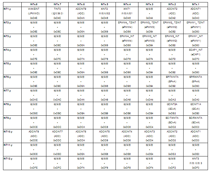
interrupt void TINT0_ISR(void) // CPU-Timer 0
{
// Insert ISR Code here
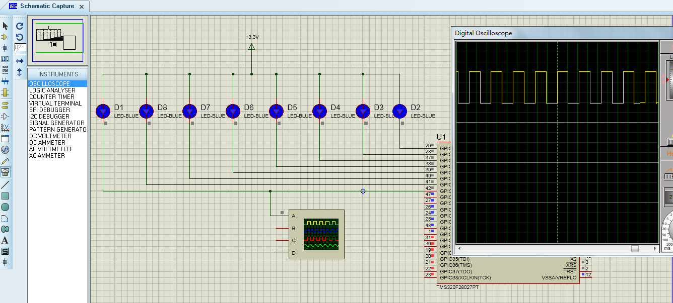
GpioDataRegs.GPATOGGLE.all=0x000000ff;
// To receive more interrupts from this PIE group, acknowledge this interrupt
PieCtrlRegs.PIEACK.all = PIEACK_GROUP1;
// Next two lines for debug only to halt the processor here// Remove after inserting ISR Code//asm (" ESTOP0");//for(;;);
}
编写主函数:
void main(void)
{
// Step 1. Initialize System Control:// PLL, WatchDog, enable Peripheral Clocks// This example function is found in the DSP2802x_SysCtrl.c file.
InitSysCtrl();
// Step 2. Initalize GPIO:// This example function is found in the DSP2802x_Gpio.c file and// illustrates how to set the GPIO to it's default state.
InitGpio();
// Step 3. Clear all interrupts and initialize PIE vector table:// Disable CPU interrupts
DINT;
// Initialize PIE control registers to their default state.// The default state is all PIE interrupts disabled and flags// are cleared.// This function is found in the DSP2802x_PieCtrl.c file.
InitPieCtrl();
// Disable CPU interrupts and clear all CPU interrupt flags:
IER =0x0000;
IFR =0x0000;
// Initialize the PIE vector table with pointers to the shell Interrupt// Service Routines (ISR).// This will populate the entire table, even if the interrupt// is not used in this example. This is useful for debug purposes.// The shell ISR routines are found in DSP2802x_DefaultIsr.c.// This function is found in DSP2802x_PieVect.c.
InitPieVectTable();
// Step 4. Initialize all the Device Peripherals:// This function is found in DSP2802x_InitPeripherals.c// InitPeripherals(); // Not required for this example// Step 5. User specific code:
GpioDataRegs.GPADAT.all=0x00000000; //GPIO0-GPIO31 initial value are 0
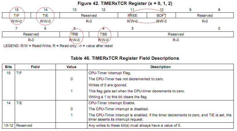
CpuTimer0Regs.TCR.bit.TIE=1;
StartCpuTimer0();
EALLOW;
PieCtrlRegs.PIEIER1.bit.INTx7 =1;
PieCtrlRegs.PIECTRL.bit.ENPIE =1;
IER =0x0001;
EINT;
EDIS;
while(1)
{
// GpioDataRegs.GPATOGGLE.all=0x000000ff;// DELAY_US(1000);
}
}